Integrating Spheres
Integrating spheres are frequently used for measurement of solid samples using a UV-VIS spectrophotometer. These integrating spheres are introduced here.
1.Introduction
Integrating spheres have a spherical-shaped inner surface and inner wall made of light scattering material, such as barium sulfate, having high reflectance. Integrating spheres are effective in causing a light beam (measurement light) entering the sphere to scatter uniformly.
Integrating spheres have a hole (aperture) at the position irradiated by the measurement light. When measuring the measurement light which passes through the sample and enters the sphere, the sample is placed at this aperture. The detector is installed at an aperture (mainly, at the top or bottom of the integrating sphere) where it is not directly irradiated by the measurement light.
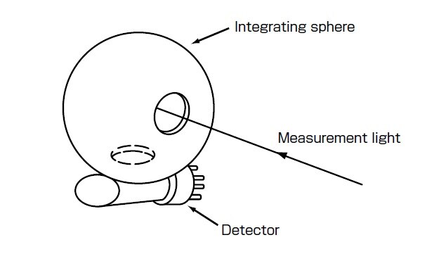
Fig.1 Schematic of Integrating Sphere
Integrating spheres are mainly used to measure samples having scattering properties or samples such as optical lenses that refract light. When measuring the transmittance of lenses that condense the measurement light after it has passed through the lens, as in the method where light is directly detected by a regular detector, the measurement light strikes the light-sensitive surface of the detector when performing baseline correction (100 % alignment) as shown in Fig. 2 (a). However, light after the sample is irradiated protrudes from the light-sensitive surface of the detector, preventing correct measurement from being performed. With a sample having scattering properties, light that is scattered after the sample is irradiated cannot reach the lightsensitive surface of the detector. When an integrating sphere is used to measure a sample, correct measurement can be performed since all measurement lights are irradiated on the light-sensitive surface of the detector after being diffused inside the integrating sphere at both baseline correction and sample measurement, as shown in Fig. 2 (b).
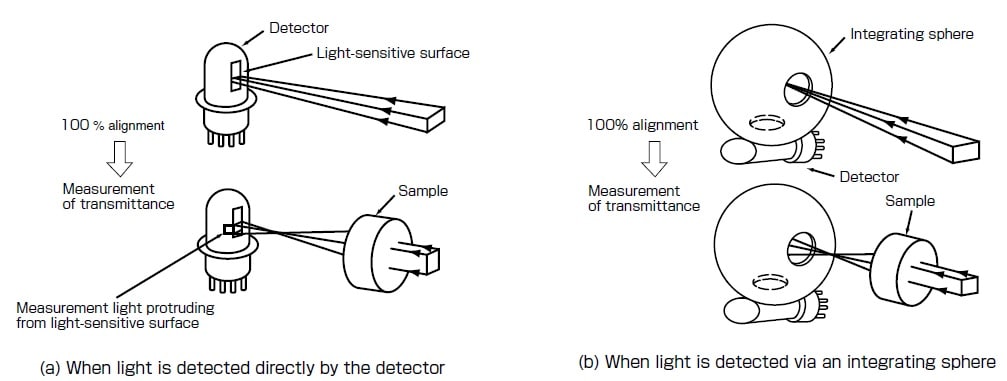
Fig. 2 Comparison of Direct Light Detection and Measurement Using Integrating Sphere
Transmittance measurement and reflectance measurement using an integrating sphere are introduced on the following pages.
2. Transmittance Measurement
As shown in Fig. 3, baseline correction is performed without a sample present at the aperture of the integrating sphere. When there is an aperture on the reflection side of the integrating sphere, a standard sample (e.g. white board filled with barium sulfate) is placed at this aperture. In regular transmittance measurement, both the scattered component and linear component that have passed through the sample are measured, as shown in Fig. 4.
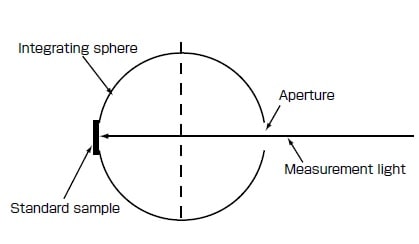
Fig. 3 Baseline Correction
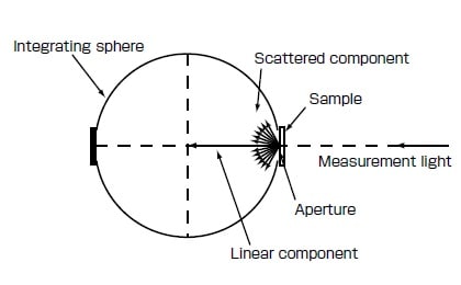
Fig. 4 Schematic of Transmittance Measurement
To perform transmittance measurement of only the scattered component, place the sample with the aperture on the reflection side open as shown in Fig. 5.
Haze (turbidity) measurement of a suspension sample called can also be performed by transmittance measurement. Baseline correction is performed with the standard sample placed on the reflection side as shown in Fig. 3. Next, measurement is performed either with a light trap (tube for absorbing linear component light to prevent it from being introduced to the detector) installed at the reflection side, as shown in Fig. 6, or with the sample placed at the aperture and with the reflection side open. Turbidity can be obtained from these measurement values. To perform measurement more exactly, measure with the light trap installed or with the reflection side open, and then calculate correction with the resulting measurement value set as turbidity "0."
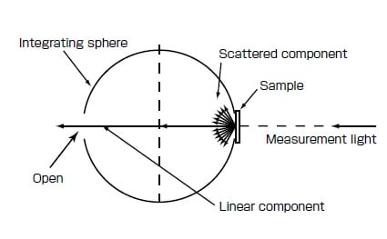
Fig. 5 Transmittance Measurement of Only Scattered Component
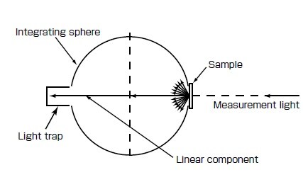
Fig. 6 Schematic of Haze Measurement
A slight difference sometimes occurs between the measurement result obtained by the integrating sphere of the spectrophotometer and the measurement value obtained by an exclusive haze meter since the irradiation state of the measurement light on the sample and the opening state, etc. of the integrating sphere are different.
3. Reflectance Measurement
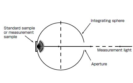
Fig. 7 Schematic of Reflectance Measurement
As shown in Fig. 7, after baseline correction is performed with the standard sample (e.g. white board filled with barium sulfate) placed at the position (reflection position) irradiated by the measurement light after it has entered the aperture and passed through the inside of the integrating sphere, the standard sample is replaced with the sample to be measured at the same position, and measurement is performed.
Reflectance measurement using an integrating sphere is called relative reflectance measurement since reflectance with respect to the standard sample is measured. Accordingly, changes (e.g. changes over time) in the reflectance of the standard sample affect the measurement value of the sample. Also, note that reflectance changes when the standard sample is changed.
There are two types of reflectance measurement, diffuse reflectance and total reflectance. With diffuse reflectance measurement, a normal (0°) measurement light is irradiated on the sample, as shown in Fig. 8. The diffuse reflectance component is diffused inside the integrating sphere, and the specular reflectance component exits to the outside of the integrating sphere from the hole at which the measurement light entered.
For this reason, diffuse reflectance measurement involves only the diffuse reflectance component. With total reflectance measurement, however, the measurement light is irradiated tilted 8° from the normal of the sample, as shown in Fig. 9. With this measurement method, the diffuse reflectance component is diffused inside the integrating sphere, in the same way as in diffuse reflectance measurement, and the specular reflectance component is diffused inside the integrating sphere since it strikes the integrating sphere's inner wall. For this reason, total reflectance measurement involves both the specular reflectance component and the diffuse reflectance component.
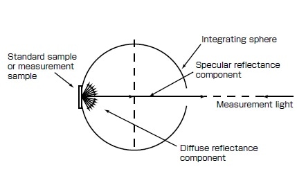
Fig. 8 Diffuse Reflectance Measurement
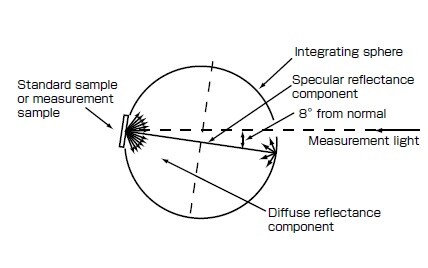
Fig. 9 Total Reflectance Measurement
With measurement using an integrating sphere, the light intensity is 1/100 to 1/1000 as compared with measuring light received directly by a detector. So, noise increases when measurement is performed at the same conditions as when light is received directly by a detector. To reduce noise, the light intensity must be increased. This can be remedied by widening the slit on a spectrophotometer.
Generally, the diameter of the inner wall of integrating spheres used in spectrophotometers is 60 mm. Some integrating spheres have an inner wall diameter of 150 mm. These have a smaller aperture ratio and higher diffusion properties, so they are less likely to be affected by the scattering state of the sample. However, due to the greater amount of space in the integrating sphere, the intensity of light incident on the detector decreases, resulting in increased noise. The aperture ratio refers to the area of the hole with respect to the entire area including the hole on the inner wall of the integrating sphere.
4. Conclusion
An integrating sphere allows measuring samples that cannot be measured properly by the method where light is directly received by a regular detector. It is recommended to use an integrating sphere when measuring samples, such as semi-transparent or opaque solutions and lenses, that change the direction of light.