Instrument Validation and Inspection Methods
The theme of this UV TALK LETTER is the instrument validation of UV-VIS spectrophotometers. Instrument validation is essential for determining the condition of your instrument. Here, we will give details of what validation is and how to do it.
1. What is Validation?
At sites where products are developed and manufactured, a variety of equipment is used to create products through a complex series of work processes. To state that such products meet the expected quality standards, it is important to verify that the plant, equipment, and operational procedures are free of problems.
Verification procedures must be established to ensure that the details of the verification are consistent, regardless of who performs it. The series of processes from performing the verification according to a defined procedure to documenting the verification results is generally known as "validation".
Validation can be performed on a diverse range of objects, from tangible items such as plant and equipment to intangible work procedures and processes. This UV TALK LETTER describes details about the instrument validation of UV-VIS spectrophotometers.
2. Instrument Validation of a UV-VIS Spectrophotometer
A spectrophotometer shines light at various wavelengths onto the sample and investigates the degree of absorption, reflection, and transmission of the light to perform qualitative or quantitative analysis of the sample. So, what sort of performance does a spectrophotometer offer?
JIS K0115 "General rules for molecular absorptiometric analysis" prescribes the performance items that should be displayed by the instrument, as shown in Table 1.
It can be seen from Table 1 that the generic term "performance" encompasses various conditions depending on the point of focus. Instrument validation of a spectrophotometer involves selecting the items required to manage and determine the status of the instrument from among these performance items, and verifying them.
| Performance Items | |
|---|---|
| Wavelength accuracy | Stray light |
| Wavelength repeatability | Baseline stability |
| Photometric accuracy | Baseline flatness |
| Photometric repeatability | Noise level |
| Resolution | |
Table 1 Performance Items Listed in JIS K0115
3. Performing Instrument Validation
The actual philosophy and method of performing instrument validation are described below using several performance items as examples.
Wavelength Accuracy
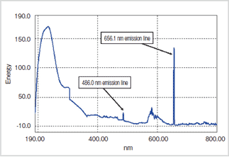
Fig. 1 Emission Lines of a Deuterium Lamp
The emission lines of a deuterium or low-pressure mercury lamp or the absorption peaks of an optical filter for wavelength calibration are generally used to verify the wavelength accuracy.
Fig. 1 shows the energy spectrum of a deuterium lamp. A deuterium lamp is known to exhibit sharp energy peaks (emission lines) at 656.1 nm and 486.0 nm wavelengths. Consequently, the instrument’s wavelength accuracy can be verified by measuring the energy spectrum of a deuterium lamp, investigating the wavelength of the peak near 656.1 nm, and then comparing its wavelength value to 656.1 nm.
For example, if the detected peak wavelength is 656.2 nm, the error from the true 656.1 nm value is 0.1 nm, and this becomes the wavelength accuracy of the instrument.
How many multiple emission lines (or absorption peaks) should be used to confirm the wavelength accuracy and what error is permitted depends on the level of instrument performance required for the development and manufacture of the product. In cases where a sample spectrum is measured and the peaks must be specified within an error of 1 nm, a wavelength accuracy of 0.1 nm is probably adequate.
Stray Light
Stray light is light outside the specified wavelength that shines onto the sample. For example, when measuring the absorbance using light at 220 nm, accurate measurements are not possible if a lot of light at wavelengths other than 220 nm hit the sample. Let us consider the case of 0.01 % stray light outside the specified wavelength. Due to the effects of the stray light, a sample with 1 % transmittance (2 Abs) appears to have a transmittance of 1.01 % (1.9957 Abs). Alternatively, a sample with 0.01 % transmittance (4 Abs) appears to have a transmittance of 0.02 % (3.6990 Abs). That is, errors of 0.0043 Abs and 0.3010 Abs, respectively, occur. This case reveals that the effects of stray light increase as the sample absorbance increases.
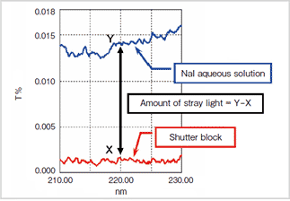
Fig. 2 Stray Light Measurements Using Nal Aqueous Solution
The presence of stray light causes distortion in the calibration curve. Consequently, an instrument with low stray light is required for the quantitation of high-concentration unknown samples (with high absorbance) using a calibration curve created with standard samples.
An aqueous solution that is known to not transmit light at a specific wavelength, such as sodium iodide (Nal), is used to evaluate the amount of stray light. For example, an aqueous solution of Nal does not transmit light at 220 nm. Initially, the transmittance is measured with a shutter block that completely shuts out all light mounted in the sample compartment (transmittance X). Next, the transmittance is measured with the aqueous solution of Nal in the sample compartment (transmittance Y). The instrument’s stray light is defined as (Y – X). This value is used to evaluate the level of stray light. Fig. 2 shows a schematic diagram of this situation.
The aim of instrument validation is to confirm that the instrument offers adequate performance for the inspection and manufacture of products. When performing an actual validation, it is important to select the appropriate inspection items and to set the evaluation criteria based on a sound understanding of the required instrument performance.
4. Validation Is Diagnosis of the State of the Instrument
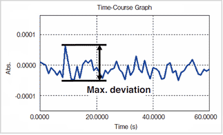
Fig. 3 Noise Level Measurement Results
A spectrophotometer is made up of many components, some of which are consumables that deteriorate according to the time and frequency of operation. Instrument validation is also useful for determining the state of the constituent components of the instrument.
Let's consider the noise level as an example. The noise level is one indicator of the condition of the light source (lamp) in the spectrophotometer. The noise level is defined as the maximum deviation (maximum distance between peak and trough) of the absorbance measured over one minute at a specific wavelength near 0 Abs. Fig.3 shows the graph of a measured noise level.
As the relative noise increases when the emitted light intensity of the lamp drops off over time, the noise level becomes higher. A higher noise level means that the data reproducibility is lower. This has a negative effect when accurate photometric values are required.
When it is necessary to detect extremely small absorption peaks, it may not be possible to detect the peaks correctly if the noise level is so high that they become buried in the noise.
The optical system of a spectrophotometer contains various mirrors for focusing and forming a spectrum. The surfaces of these mirrors can deteriorate over time. It is also possible for dust and dirt from the atmosphere to adhere to the mirror surfaces due to the environment where the instrument is installed. For example, the deterioration of a mirror that forms the spectrum can be one cause of the increase in stray light described above.
Therefore, instrument validation can provide valuable information to diagnose the condition of an instrument. It is recommended to perform periodic instrument validation to continuously understand and manage the state of the instrument. It is also important to validate an instrument after consumables are replaced or the instrument is moved to a different place.
5. Automated Instrument Validation Using Software
A diverse range of performance items must be checked during instrument validation. Doing so manually takes a lot of time. It is easy for errors to occur during such a complex inspection procedure.
A program designed to automate the measurements and calculations necessary for validation operations can significantly reduce the effort needed for instrument management.
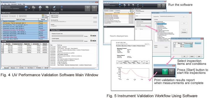
Shimadzu supplies dedicated UV Performance Validation Software for the instrument validation of UV-VIS spectrophotometers. Fig. 4 shows a screen shot from the UV Performance Validation Software.
This software simplifies setup of the inspection items, inspection conditions, and the evaluation criteria and automates the process through measurement, calculation, and evaluation.
It offers a variety of functions to support instrument validation work, including management of inspection tools such as optical calibration filters, and printout of validation results reports.
Fig. 5 shows an example of the instrument validation workflow using the software.
It can be seen that the software permits accurate and efficient instrument validation.
6. Conclusions
This UV TALK LETTER introduced the following points:
- Instrument validation is important to determine the status of instruments used for the development and manufacture of products.
- To perform an actual instrument evaluation, select the required performance items and set the appropriate evaluation criteria for the inspection.
- The effective application of a validation program permits accurate and efficient instrument validation.
This UV TALK LETTER described instrument validation.
We hope it gives you an understanding of how to manage and monitor the condition of your instrument.
The booklet addresses a range of UV related topics and useful analysis information and know-how using Shimadzu UV spectrophotometers.