Introduction to LC-MS Part6
Part6
Introduction to LC-MS - Part 5 describes the mechanism used in magnetic sector mass spectrometers to separate ions by mass. In Part 6, we continue the discussion, focusing on the ion mass separation mechanism and characteristics of quadrupole, ion trap, and time-of-flight systems.
Quadrupole MS
As the name suggests, quadrupole MS systems contain four parallel cylindrical metal rods (electrodes with a hyperboloidal interior surface) inside a vacuum chamber, positioned equidistant from the center axis (Figure 1).
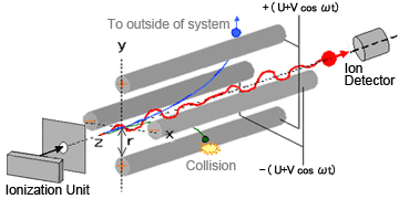
Fig. 1 Diagram of Quadrupole MS
Ions generated in the ionization unit are accelerated in the Z-direction by a relatively-weak voltage of only a few dozen volts. Theses ions pass through a tiny orifice and enter the quadrupole area. Voltage of the same polarity is applied to diagonally-opposite poles and opposite voltage polarity is applied to adjacent poles. When a combination of direct current voltage U and high-frequency alternating current voltage V cos ωt is applied to each pole (where, ω is frequency and t is time), an electric field with a rapidly varying phase is generated within the quadrupole.
Consequently, ions passing through this electric field oscillate in the X and Y directions. When a given set of conditions (for U, V and ω) are applied, certain ions in a specific mass-to-charge ratio (m/z) range maintain a stable oscillation and pass through the quadrupole to reach the detector. On the contrary, the oscillations of ions with other m/z values become unstable, causing them to collide with the poles, fly out of the system, or not be detected.
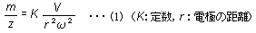
The oscillation of ions within the quadrupole is known to occur according to an equation called the Mathieu equation. Regardless of the ion's initial velocity or initial position, the motion of ions satisfies equation (1).
A simple diagram illustrates how the equation is solved (Figure 2). The conditions required for stable ion oscillation are determined by the mass m and oscillation frequency ω of the ion. This is illustrated as the areas enclosed by the lines in Figure 2. The region of stability is different for ions with masses m1, m2, and m3. Consequently, if the voltage is varied while keeping the ratio between the direct current voltage and high-frequency alternating current voltage constant (straight scan line (1)), so that the line (1) passes through respective regions of stability for m1, m2, and m3, ions with masses m1, m2, and m3 can be passed through the quadrupole consecutively in order. In this way, a mass spectrum can be obtained for ions with masses ranging from small to large.
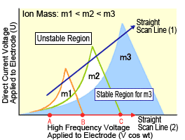
Fig. 2 Stable Regions for Ions in Quadrupole MS System (Mathieu diagram)
Characteristics of Quadrupole MS
Since quadrupole MS systems are compact and simple, they are simpler to operate and easier to maintain and are relatively less expensive. Consequently, they have become widely adopted as a general-purpose instrument. Mass spectrometers require high vacuum levels, whereas quadrupole MS systems are able to separate ions at lower vacuum levels (10-2 to 10-3 Pa) than other mass separation methods. Therefore, even if they are interfaced with a GC or LC unit, the drop in vacuum level caused by the interface has minimal effect on mass separation performance, making it the best suited for interfacing with chromatographs.
Furthermore, with a maximum scan speed of about 6000 amu/sec, it is capable of measuring at higher scan speeds than magnetic sector MS systems, and its mass measurement range of up to about 2000 m/z enables qualitative analysis in a practical range of molecular masses. In addition, it allows high-speed switching, which enables simultaneously monitoring multiple selected ions (SIM) for high-sensitivity simultaneous quantitative analysis of multiple components. In this way, quadrupole MS systems can be used for both qualitative and quantitative analysis, making it the de facto standard system among mass spectrometers.
Ion Trap MS
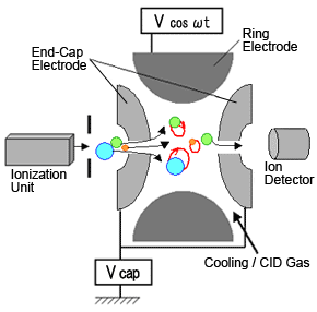
Fig. 3 Diagram of Ion-Trap MS
Ion trap type MS systems apply the same quadrupole principle. In these systems, the motion of ions within the mass analyzer follows the Mathieu equation. These systems consist of a donut shaped ring electrode sandwiched between two end-cap electrodes. An ionization unit is located at the entrance and a detector at the exit (Figure 3).
Just like a quadrupole system, the internal surface of electrodes are hyperboloidal, which can be thought of the entrance and exit of a quadrupole connected in a ring shape.
Normally, the ion trap is used without applying the direct current voltage U to the electrodes, which corresponds to operation along the horizontal axis in Figure 2.
To measure a spectrum, end-cap electrodes are grounded, then a low high-frequency voltage is applied to the ring electrode. Then ions with the required m/z range are introduced, where they are all temporarily trapped inside the electrode. This state is indicated in Figure 2 as point A. It shows that ions with masses m1, m2, and m3 are experiencing stable oscillation. Next, the high-frequency voltage is gradually increased (straight scan line (2)), while keeping U equal to zero. Then the oscillation of m1 becomes unstable at point B and m2 becomes unstable at point C, at which time these ions are discharged via the hole in the end-cap electrode.
Quadrupole MS systems separate and detect masses by letting oscillating ions pass through the quadrupole to reach a detector, whereas ion trap MS systems separate and detect masses by discharging ions with unstable oscillations from the system.
Characteristics of Ion Trap MS
As the name implies, ion trap MS systems trap the generated ions before separating them by mass. Consequently, they cannot perform SIM measurements for transmission type mass spectrometry. Furthermore, only a limited quantity of ions can be trapped, resulting in a narrower dynamic range than quadrupole MS systems.
However, since all trapped ions are detected, it provides higher sensitivity in scanning analysis than quadrupole models. In addition, it enables trapping specific ions, then fragmenting them and detecting the resulting fragment ions. Therefore, it is considered a mass spectrometer specialized for qualitative analysis.
Time-of-Flight MS
Time-of-flight MS systems have a simple construction. All that is needed is an accelerator and detector inside a strong vacuum (Figure 4).
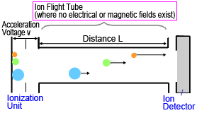
Fig. 4 Diagram of Time-of-Flight MS
Ions generated in an ionization unit are extracted in pulses and accelerated by a high acceleration voltage (10 to 30 kV) applied between electrodes, then each ion flies at a constant velocity through a drift region, free of any electric or magnetic fields, to reach a detector.
If ions are accelerated by a constant voltage, then a kinetic energy corresponding to the voltage is applied to all ions. This can be described by equation (2), where the velocity v of ions accelerated by a constant kinetic energy is higher for ions with smaller masses and lower for ions with larger masses.

(m: mass of ion, v: velocity of ion, z: charge number, e: elementary charge, and V: acceleration voltage)
Given the distance L between the ionization unit and detector, the flight time for an ion of mass m is described by equation (3).
Since the distance L, acceleration voltage V, and elementary charge e are all constant in equation (3), the time-of-flight T is proportional to the square root of the m/z ratio. Given a fixed flight distance, ions with smaller m/z values reach the detector sooner, whereas ions with large m/z values reach the detector later.Therefore, a mass spectrum can be obtained by converting these differences in time into differences in mass.
Furthermore, if there is no limit to the flight time T in equation (3), then the measurement mass range is theoretically unlimited as well.
Characteristics of Time-of-Flight MS
Due to its operating principle, time-of-flight MS systems do not ionize molecules until after the previous group has reached the detector. Therefore, it seems to have good compatibility with ionization methods that ionize molecules in pulses, such as laser ionization. The analytical technique has been extremely useful for proteomics using MALDI-TOFMS systems, where proteins are identified by comparing measurements of fragmented peptides with a database. When used for LC-MS, the continuous ion beam entering the unit must be converted to a pulse.
Early time-of-flight MS systems had low resolution, which was considered its weakness, but due to the development of technology that minimizes the differences in the kinetic energy of ions, such as reflectron and pulsed extraction methods, time-of-flight MS systems are currently being used for high-resolution mass spectrometry.
Selecting an MS Unit to Serve as an LC Detector
Mass spectrometers are now used for an extremely diverse range of applications, each with its own characteristics. Therefore, it is not easy to decide in a simple manner which type of MS is optimal. In terms of price and ease-of-operation, quadrupole-based products have been increasing in market share for LC-MS applications. In contrast, ion trap and time-of-flight models offer performance not available from quadrupole models, so their popularity is also continuing to increase. This means the system must be selected based on objectives, such as whether high sensitivity is required, high resolution is required, or a compact general-purpose system is required. The most important thing is to choose a system that allows benefiting from the advantages offered by each ionization method and mass separation method.
I hope the above explanations have been helpful. (Ym)