Spectral Emissivity Measurement Using FTIR Spectrophotometry
As the issue of global warming becomes increasingly serious, various measures aimed at reducing CO2 emissions are being implemented on a global scale. A representative example of this is the introduction of natural forms of energy (e.g., wind power, hydraulic power, and sunlight) as substitutes for fossil fuels, which are a major cause of CO2 emissions. At the same time, from the viewpoint of energy conservation, it is also important to review our lifestyles and eliminate unnecessary energy consumption. Far-infrared radiation materials are used as heaters and refractory materials in industrial products and household electrical appliances, heating and insulating equipment in particular. There are increasing expectations that the efficient use of such materials will contribute to energy conservation.
Here, I present a measurement system and some measurement examples related to spectral emissivity spectra, which provide basic data that can be used to evaluate far-infrared radiation materials.
1. Spectral Emissivity
"Emissivity" is defined by Japanese industrial standard JIS Z 8117 1) as "the ratio of the radiant emittance of a body to the radiant emittance of a black body at the same temperature as that body." "Spectral emissivity" is defined as "the result of expressing the emissivity as a function of the component wavelengths (wavenumbers or frequencies)." 1)
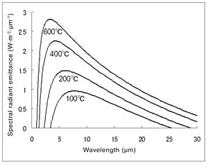
A black body is "an idealized object that perfectly absorbs radiation at every wavelength." 1) The fact that the energy radiated from a black body can be expressed as a function of the wavelength and the temperature of the body is known as "Planck's law." Fig. 1 shows the spectral radiant emittance of a black body at temperatures of 100, 200, 400, and 600 °C calculated with Planck's law. (The vertical axis represents logarithmic values.)
In actual measurement, a black body furnace is used as a body whose properties approach those of an ideal black body. The emissivity of samples is measured using the black body furnace as a reference.
Planck's law
Meλ = (C1/λ5) / [exp(C2/λT)-1] (W·m-2·μm-1)
Here, C1: First radiation constant, C2: Second radiation constant
C1 = 2πhc2 = 3.741771 × 10⁻¹⁶ (W·m2),
C2 = hc/k = 1.438775 × 10⁻² (m·K)
2. Spectral Emissivity Measurement System
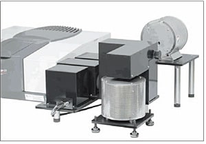
Fig. 2 Appearance of Spectral Emissivity Measurement System
A spectral emissivity measurement method using an FTIR spectrophotometer is detailed in Japanese industrial standard JIS R 1801 2). Here, I present an emissivity measurement system consisting of an FTIR spectrophotometer (IRPrestige-21), a black body furnace, a sample heating furnace, a temperature controller, and a separate optical system. A photograph of the system is shown in Fig. 2.
JIS R 1801 2) specifies the method for performing measurement, using an FTIR spectrophotometer, in a range from "a wavelength of approx. 2.5 μm to approx. 25 μm." There is no clear definition of the wavelength range of "far-infrared," even in JIS Z 8117. 1) The definition varies with the industry; for example, the Japan Far Infrared Rays Association specifies a range of "the wavelength from 3 μm (micron) to 1 mm (millimeter)." Even if the sample is a "far-infrared radiation material," the type of measurement is referred to as "(infrared) emissivity measurement" or "radiation factor measurement," and not "far-infrared emissivity measurement," because the spectroscopic definition of far-infrared light is light of a wavelength minimum of 25 μm.
Explanations of the black body furnace, the sample heating furnace, and the FTIR spectrophotometer that form part of the system are given below.
2.1 Black Body Furnace
A black body is an object that completely absorbs any electromagnetic radiation that falls on it across all wavelengths. There are no true (i.e., ideal) black bodies in nature. Therefore, in emissivity measurement, a black body furnace is used as a body whose properties approach those of an ideal black body. A black body furnace is a device that closely replicates a black body, and is used as an illuminant.
According to JIS Z 8117, 1) "there are black body furnaces in which a hollow formed out of metal, graphite, a ceramic, or some other suitable material is kept at a temperature in the range 300 to 1,500 K, and the radiant flux emitted from an aperture in the hollow is utilized." In general, a black body furnace has the kind of structure shown in Fig. 3, where a hole with a diameter of approx. 2 cm is opened in a spherical hollow surrounded by heaters.
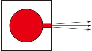
Fig. 3 Black Body Furnace
2.2 Sample Heating Furnace
A sample heating furnace is a device used to heat samples.
There are furnaces that keep the sample in a vertical position but usually the sample mounting is horizontal, as shown in Fig. 4. Samples with diameters of up to a few centimeters can be set. As the spot size required for measurement is approx. 1 cm in diameter, note that the measurement results may be affected by a small positional displacement if the sample diameter is only around 1 cm.
Also, because it is difficult to use large samples with sample heating furnaces designed for temperatures exceeding 1,000 °C, logistical coordination may be required to determine the specifications suitable for the samples.
Regarding sample form, measurement is usually possible only for plate-like samples. Accurate measurement is not possible for curved or powdered samples. This is because the temperature is not even over the surface of such samples, making it impossible for the surface temperature to be measured accurately.
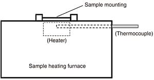
Fig. 4 Sample Heating Furnace
The black body furnace and sample heating furnace are equipped with thermocouples in order to monitor the
temperature, and temperature control is performed by a temperature controller.
2.3 Fourier Transform Infrared (FTIR) Spectrophotometer
An FTIR spectrophotometer is a device with a built-in infrared light source that irradiates the sample in a sample compartment and obtains absorption spectra. When an FTIR spectrophotometer is used for emissivity measurement, the built-in infrared light source is turned OFF, and the spectrophotometer is set to analyze the radiation emitted from the black body furnace and the sample heating furnace. Because external radiation is introduced into the spectrophotometer in place of the radiation emitted by the light source, a separate optical system is required. In the photograph shown in Fig. 2, the separate optical system is set up on one side of the FTIR spectrophotometer, and the sample heating furnace and black body furnace are respectively positioned in front of and behind the optical system.
This system can also support standard measurement using the sample compartment.
3. Examples of Emissivity Measurement
The first step of the measurement procedure consists of
setting the temperatures of the black body furnace and sample heating furnace to the temperature required for measurement. After the temperature of the black body furnace stabilizes at the set temperature, the radiant energy is measured as the background level. Then, the optical path is switched to the sample heating furnace, and after the sample surface is heated to the set temperature, the radiant energy emitted by the surface is measured. It is important to ensure that the temperatures of the black body furnace and the sample surface are the same. Because temperature control of the sample heating furnace is performed using the temperature in the area near the heater where the thermocouple is installed, the sample surface temperature is lower than the set temperature of the sample heating furnace. The sample surface temperature can be accurately made to conform with the temperature of the black body furnace by, for example, installing a thermocouple on the sample surface, or coating the sample surface with black coating material and measuring the emissivity, and adjusting the temperature as appropriate.
Examples of the analysis of an alumina ceramic and a glass plate are presented below.
3.1 Analysis of Alumina Ceramic
An alumina ceramic circular disc with a thickness of 1 mm was heated to 450 °C, and the spectral emissivity was measured. Fig. 5 shows the measurements obtained for the radiant energy of the black body furnace and the sample on a graph with the horizontal axis representing the wavelength. The spectral emissivity was obtained by calculating the ratio of the two sets of measurements, and the result of this is shown in Fig. 6. It can be seen that, in a wavelength range of approximately 6 to 10 μm, the emissivity is close to 100 %. If the spectral emissivity is known, multiplying the black body spectral radiant emittance obtained with Planck's law, which was given previously, by the emissivity of the sample makes it possible to obtain the spectral radiant emittance of the sample. Fig. 7 shows the spectral radiant emittance for a temperature of 450 °C obtained with Planck's law and the spectral emissivity of the alumina ceramic.
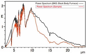
Fig. 5 Radiant Energy of Black Body Furnace and Alumina Ceramic
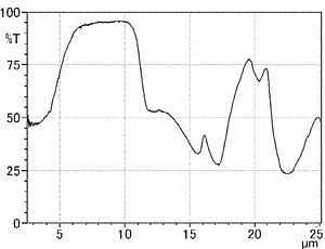
Fig. 6 Spectral Emissivity Spectrum of Alumina Ceramic
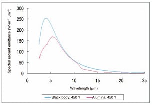
Fig. 7 Spectral Radiant Emittance at 450 °C
3.2 Analysis of Glass Plate
Fig. 8 (a) shows the spectral emissivity spectrum obtained for a glass plate with a thickness of 5 mm at a temperature of 300 °C. Fig. 8 (b) and Fig. 8 (c) show the reflection spectrum and transmission spectrum obtained for the same sample.
Taking 1 as the total amount of energy in the light that strikes the object, the law of conservation of energy gives the following:
1 = α + ρ + τ
(α: Absorptance, ρ: Reflectance; τ: Transmittance)
In the case of an opaque body, τ = 0, and applying Kirchoff's law, which states that the emissivity, ε, of a body equals its absorptance at thermal equilibrium, the emissivity can be obtained by subtracting the reflectance from 1 (ε = 1 − ρ).
The results shown in Fig. 8 indicate that, at wavelengths greater than 4 μm, the transmittance of this glass is almost 0 %, so ε ≈ 1 − ρ. It can be seen from this that the emissivity spectrum shown in Fig. 8 is reasonable.
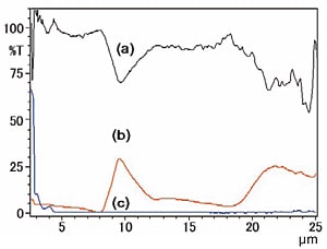
Fig. 8 Spectral Emissivity Spectrum (a), Reflection Spectrum (b), and Transmission Spectrum (c) of Glass Plate
4. Summary
In the 1970s, Japan experienced energy crises that resulted from a disruption of the world's oil supplies. This experience greatly encouraged the country to develop far-infrared radiation materials as a means of energy conservation.
Now, faced with the issue of global warming, we are entering an age in which new energy sources and energy conservation are pressing issues. While the efficient use of far-infrared radiation materials is being promoted with increasing intensity, it is important to advance a correct understanding of spectral emissivity measurement, the technique used to evaluate these materials. Dr. Hiroo Takashima's book 3) provides a detailed explanation on the effects and characteristics of far-infrared radiation, and includes a description of spectral emissivity measurement.
References
- Japanese industrial standard JIS Z 8117: "Glossary of Far Infrared Radiation Terms"
- Japanese industrial standard JIS R 1801: "Method for measuring spectral emissivity of ceramic radiating materials for infrared heaters by using FTIR"
- Hiroo Takashima, "Far-Infrared Engineering Made Easy," Kogyo Chosakai Publishing, Inc., 1988.