Polarization Measurement of Film Using Single-Reflection ATR
There is a tendency for the long axes of the molecules of stretched polymers to line up in the stretching direction, and the extent of this can be ascertained using polarization measurement. Film samples are usually analyzed with a transmission method using a polarizer. Here, however, an example of polarization measurement using ATR is presented.
1. Polarization Measurement Using the Transmission Method
Polarization measurement uses linearly polarized light, which has an electric field that only oscillates in a certain direction. In order to create this linearly polarized light, a polarizer is required. Polarizers created by incorporating a wire grid into a KRS-5 substrate are commonly used.
The procedure of polarization measurement using the transmission method is as follows. First, BKG is measured with the polarizer at an angle of 0° (i.e., with the electric field oriented in a perpendicular direction), and then the sample is measured with its stretching direction aligned with the vertical direction. (At this time, the polarization direction and the direction of the stretching axis are parallel.) Then, the sample is rotated by 90° so that the stretching direction is perpendicular to the polarization direction and measured. The ratio of the absorbances, A|| and A⊥, of the spectra obtained in these two configurations, namely, with polarization parallel and perpendicular to the stretching direction, represents the dichroic ratio.

2. Polarization Measurement Using ATR
Fig. 1 Expressions of Molecular Orientation
With the transmission method, if the film thickness is too large, the peaks may become saturated, and measurement may not be possible. ATR has the advantage of not requiring consideration of film thickness.
With single-reflection ATR, because the prism is smaller than it is with multi-reflection ATR, it is easier to rotate the sample and there is better adhesion, so spectra with good repeatability can be obtained.
One of the features of ATR polarization measurement is that, in cases of film samples with two-axis symmetry, as shown in Fig. 1, information can be obtained in relation to the orientation of the molecules with respect to the X, Y, and Z axes. In this diagram, the Y axis represents the stretching direction, the X axis the direction that is perpendicular to, and in the same plane as, the stretching direction, and the Z axis the direction that is perpendicular to the surface of the sample (i.e., the thickness direction).
Four types of measurement are required. The sample is first measured with its stretching direction aligned with the direction of light propagation, while being irradiated with (1) parallel polarized light and (2) perpendicular polarized light. Then the sample is rotated by 90° and the measurements are repeated, with (3) parallel polarized light and (4) perpendicular polarized light. Here, "parallel polarized light" refers to linearly polarized light, which has an electric field that is parallel to the plane containing the incident light and reflected light, and "perpendicular polarized light" refers to linearly polarized light, which has an electric field that lies in the plane perpendicular to the parallel polarized light. The evanescent wave generated at the reflection point by perpendicular polarized light has a vector in the X direction. The evanescent wave generated at the reflection point by parallel polarized light has vectors in the Y and Z directions.1) (See Fig. 2.)
The spectra obtained with the above procedure reflect information about molecular vibrations in the X, Y, and Z directions. Detailed methods for expressing the orientation for all three directions are referred to in the reference material1). The spectra obtained in the actual analysis of PET (polyethylene terephthalate) film are presented here.
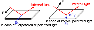
Fig. 2 Directions of Polarized Light and Evanescent Wave
3. Polarization Measurement for Stretched PET Film Using ATR
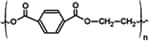
Structural Formula of PET
Fig. 3 shows the results obtained by analyzing unstretched PET film in four modes. There are hardly any differences between any of the four spectra, indicating that there is no molecular orientation.
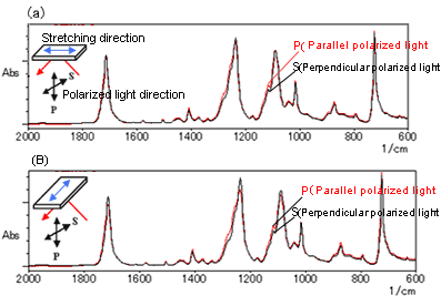
Fig. 3 Polarization Measurement Using Single-Reflection ATR Unstretched PET Film
Fig. 4 shows the results obtained with the same PET film stretched by a factor of three.
For each stretching orientation, differences can be observed in the spectra obtained with parallel polarized light and perpendicular polarized light. For example, the peak in the neighborhood of 1,340 cm-1 corresponds to the CH2 wagging vibration and the mode in which the molecules oscillate in the direction of their long axes. In Fig. 4 (a), this peak is high for parallel polarized light (P) and low for perpendicular polarized light (S). On the other hand, this is reversed in Fig. 4 (b), indicating that the molecules are oriented in the stretching direction.
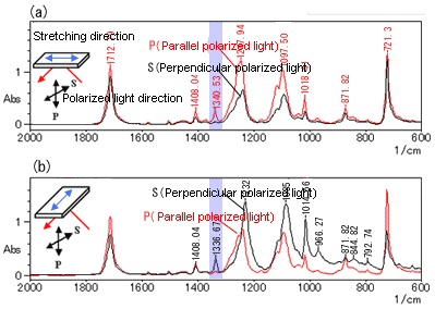
Fig. 4 Polarization Measurement Using Single-Reflection ATR PET Film Stretched by a Factor of 3
Assuming the peak at 1,410 cm-1 in Fig. 4 corresponds to in-plane bending vibration of benzene rings in a non-dichroic band, this peak was used to normalize the spectra (match peak intensity levels), then Figs. 5 (a) and (b) were obtained by generating differential spectra of the results for parallel polarized light and perpendicular polarized light shown in Figs. 4 (a) and (b).
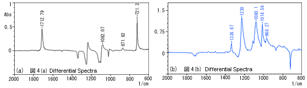
Fig. 5 Differential Spectra
Everall et al. report that, in experiments where the stretching factor was varied in the range of 1.0 to 3.5, for larger stretching factors, the degree of orientation in the stretching direction was greater while the degrees of orientation in the transverse direction (i.e., the direction in the plane of the film that is perpendicular to the stretching direction) and depth direction were smaller.1)
4. Conclusions
It has been shown here that polarization measurement using ATR is extremely effective for investigating the orientation of film surfaces. Single-reflection ATR using a diamond prism, however, does present some problems. For example, there are concerns about the effect that the localized application of large forces may have on the molecular orientation, and in the analysis of polymers with a high refractive index, the peaks in bands of strong absorbance may be lopsided. Therefore, when investigating orientation with polarization measurement using ATR, in consideration of these potential problems, it is necessary to select the optimum peaks that exhibit dichroism.
References: 1)Neil J. Everall and Arran Bibby Appl. Spectrosc. 51, 1083 (1997)