Mirrors Used with FTIR
Topics related to the internal workings of FTIR have been discussed time and again in the FTIR TALK LETTER, and this issue addresses the topic of mirrors used inside an FTIR.
1. Why is a mirror used instead of a lens?
In instruments that use light, like an FTIR, it is necessary to process light in various ways, such as focusing it or forcing its rays to travel in parallel. You may think of lenses as objects used for these purposes. Everyone has probably had the experience of using a magnifying glass to scorch a piece of paper by focusing the sun's rays at one point on the paper. In a camera, one of the most familiar devices which rely on light, multiple lenses are combined to form an image on the film (these days, most likely on a solid state image sensor like a CCD) of the picture we want to take. However, it is difficult to use a lens in an FTIR.
In order for a lens to be applicable in an FTIR, that lens must satisfy the following conditions.
|
(1) |
Have a wide wavelength range for transmission of infrared light, and be made of material that does not show large absorption within that range |
|
(2) |
Have a refractive index that is not too large |
|
(3) |
Be easy to fabricate |
|
(4) |
Be relatively inexpensive |
|
(5) |
Be environmentally-resistant |
Up to now, a material that satisfies all the properties of (1) to (5) has not yet been developed. For example, an optical element known as a beam splitter is used inside the FTIR interferometer, and the material used for this is generally potassium bromide (KBr). This potassium bromide satisfies the conditions of (1) and (2), but because it is deliquescent (property of a crystal in air that takes in water and dissolves), it must be used in a low-humidity environment. Therefore, there is a problem with respect to environmental resistance, that is, condition (5).
On the other hand, the material calcium fluoride (CaF2) is excellent with respect to conditions (2), (3), and (4). However, the range within which it transmits infrared light is narrow, barely transmitting any infrared light in the region referred to as the fingerprint region below 1000 cm-1. Thus, its application is restricted.
Due to these factors, elements through which light must pass through, like lenses and prisms, are not used in FTIR, while mirrors, which reflect light, are used.
2. Types of Mirrors
The following types of mirrors are used to fulfill the roles of lenses and prisms in the FTIR.
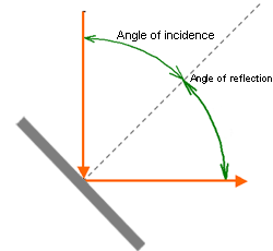
Figure 1 Plane Mirror
1) Plane mirror
As its name indicates, this is a mirror with a planar (flat) reflective surface. It is used to reflect light in a desired direction.
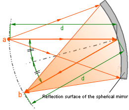
Figure 2 Principle of Spherical Mirror
2) Spherical mirror
This mirror uses part of the spherical surface as the reflection surface. Because there is point symmetry with respect to the center of the spherical surface, characteristically equal light can be created in any arbitrary direction.
(Distance to center of the sphere surface is d. Light from point a, at distance d from the sphere surface, is reflected by the spherical mirror. An image the same as a is created at point b, separated from the sphere surface by distance d.)
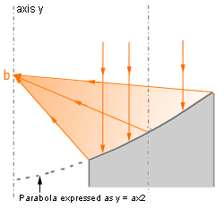
Figure 3 Principle of Parabolic Mirror
3) Parabolic mirror
A mirror with a curved surface described by the rotation of a parabola expressed as y = ax2 around axis y is a parabolic mirror. With a parabolic mirror, parallel incident light rays, illustrated by the arrows below, are concentrated at a single point. Therefore, it is used to focus parallel light rays to a single point, and to reflect light from a single point as parallel rays.
(Parallel light, as illustrated by the arrows, is reflected and focused at point b.)
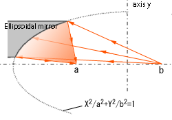
Figure 4 Principle of Ellipsoidal Mirror
4) Ellipsoidal mirror
A mirror with a portion of the curved surface described by the rotation of an ellipsoid expressed as x2/a2+y2/b2 = 1 around axis y is an ellipsoidal mirror. There are 2 focal points on an ellipsoid surface, such that when light is irradiated from either of the points, it is focused on the position of the other focal point, and this is the property that is exploited.
Specifically, it is used in the FTIR to refocus light that has been collected in the sample compartment on the infrared detector.
(Light irradiated from focal point b is concentrated at focal point a.)
3. Conclusion
Here we introduced and discussed the use of the mirror in FTIR. In the Shimadzu FTIR, the infrared light can be taken out as parallel light from the side of the instrument. When we customize specialized attachments to conduct measurement using this parallel light, we use some of the mirrors explained above in combination.