Apparatus constituting HPLC
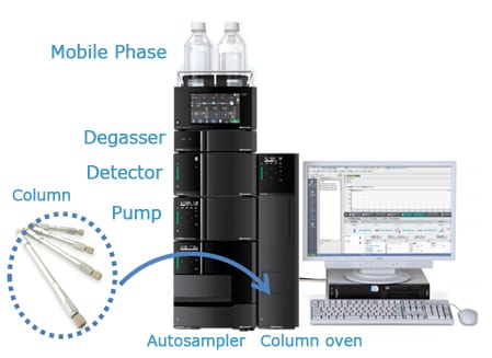
Fig.1 Appearance of HPLC
The article of “What is HPLC?” describes the overview of HPLC. A HPLC system consist of various of components, including solvent delivery pumps, a sample injector, a column oven, a detector, and a workstation. This page introduces the operating principles of main each components.
Fig.1 shows the appearance of HPLC.
1. Solvent Delivery Pump
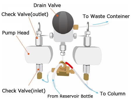
Fig.2 Inside of Solvent Delivery Pump
A stability of solvent delivery affects the precision of the retention time of compound and the calculation of peak area. Fig.2 shows the sketch of the inside of solvent delivery pump. Seeing from the front of the solvent delivery pump, it contains two pump heads and a drain valve. The mobile phase is delivered through the pump head. Drain valve is used to replace the mobile phase or remove air from the flow path. By opening the drain valve, the flow path can be switched from the downstream flow path from the pump to the drain (waste container). Each pump head has check valves at the inlet and outlet.
Fig.3 Operation of Solvent Delivery Pump
Fig. 3 shows the basic operation of a general solvent delivery pump for HPLC. A typical LC pump is based on the reciprocating piston design. The basic elements of the pump are a cylindrical pump chamber that holds the piston, a motor that operates a driving cam, a plunger seal, and a pair of check valves. Check valves consisting of tapered seats and balls are placed at the chamber inlet and outlet, respectively. When the plunger is pulled to the left in the figure, the inside of the chamber is depressurized. Then, the inside of inlet check valve is depressurized then a ball inside the check valve floats making a gap between the ball and the sheet. This action allows mobile phase to enter the pump chamber. Conversely, when the plunger moves to the right due to the action of the cam connected to the motor, the chamber is pressurized and the inlet check valve closes. Then, the outlet check valve opens and the mobile phase in the chamber flows toward the column. The pump operates these processes continuously to deliver the mobile phase.
2. Sample Injector
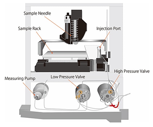
Fig.4 Inside of Autosampler
Sample injection devices that can inject sample solutions are classified into two types: manual injectors and autosamplers. A manual injector is a device that introduces a sample into a column with a syringe manually. It is easy to handle the simple mechanism, but the accuracy of sample injection depends on the operator’s skill. The autosampler is a device that affords automatic sample measurement, sample injection, and cleaning of needle. There are total volume injection method and loop injection method in the injection method. Fig.4 shows the sketch of the inside of the autosampler. The autosampler consists of a sample rack for setting sample vials, a sample needle, a sample loop, and a valve for changing the flow path of the mobile phase.
Fig.5 shows the schematic diagrams for the basic operation of sample injection in an autosampler (total-volume injection method). The mobile phase coming from the solvent delivery pumps flows through the high pressure valve, sample loop, needle, injection port, and high pressure valve to the column(a). The high pressure valve switches the flow path to separate the needle from the flow path of the mobile phase when loading a sample from the sample vial.(b)。The needle is inserted into a sample vial and then the measuring pump operates and draws the sample into the needle and the sample loop(c). The needle is inserted into the injection port and then the high pressure valve switches to the inject position to start analysis. The sample is delivered with the mobile phase through the high pressure valve to the column(d). This is a series of flow for the sample injection.
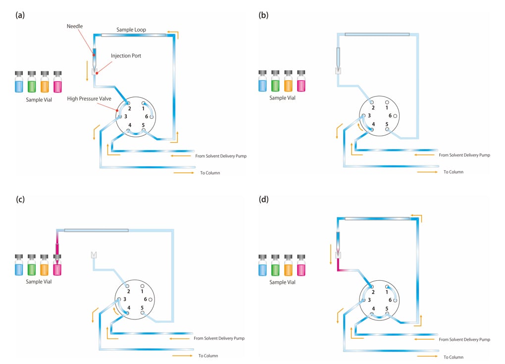
Fig.5 Basic Operation of Autosampler (Total-volume Injection)
3. Column Oven
The function of a column oven is to keep the temperature of the columns constant.
The separation of compounds using chemical interaction between the stationary phase and the target compounds is quite sensitive against temperature change. Moreover, the peak shape and retention time are not stable without the temperature control. For these reasons, a column oven is used.
There are two types of column oven, block heater type and air circulation type. Fig.6 shows the image of the inside of column ovens.
For block heater type, the column is heated on a metal block designed for a couple of assigned column sizes. Since the accuracy of temperature control would be worse if there is a space between the column and the block, installable column size and numbers are limited.
For air circulation type, columns can be installed anywhere in the oven. Therefore, the size and number of columns that can be contained are more flexible than those of the block heater type. On the other hand, the size of oven could be large because of the space for circulation system.
This air circulation type can be equipped with a mixer and a manual injector using the empty space of the chamber. It contributes to the stability of analysis in addition to the temperature control.
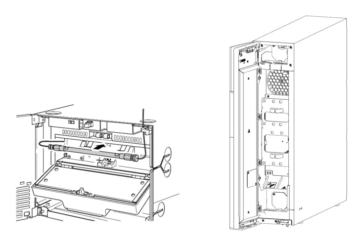
Fig.6 Inside of Column Oven
(Left : Block-Heater Type, Right : Air-Circulation Type)